
How it Works
The Lux Wind Power concept combines several structural innovations into a single architecture for large floating wind:
a cube‑framed, stackable Vertical Axis Wind Turbine module,
a floating V‑shaped array carrying 16 identical turbines for a total of 80 MW, and
a Prestressed Truss Beam (PTB) system that allows long, slender members to carry high compression loads.
This page is intended for turbine manufacturers, offshore engineering firms, and technical teams who may wish to evaluate the concept further and consider licensing the underlying IP.
80 MW with sixteen 5MW H-Style VAWT
Cube-Framed Module
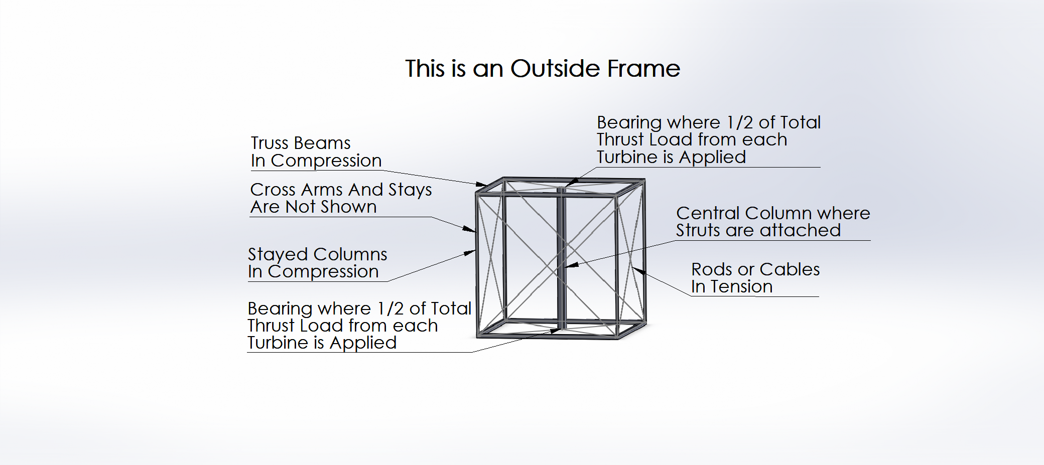
Each turbine is housed inside a cube‑shaped external frame designed so that:
Each of the 6 cube faces has:
4 edge beams (one along each side),
2 diagonal members running corner‑to‑corner in an “X”.
The diagonal members are designed to stay in tension, keeping the edge beams in pure compression with minimal bending, torsion or shear.
A vertical main shaft (Central Column) runs through the center of the cube:
Supported by bearings at the intersection of the top diagonals and at the intersection of the bottom diagonals.
Extends below the cube to drive a generator mounted under the frame or to connect to another turbine rotor.
Struts extend radially from the main shaft to support the blades, forming a vertical H‑type rotor inside the frame.
This structural approach:
Keeps the primary members in either tension or compression, rather than complex bending.
Allows a lighter frame than a typical conventional tower with the same power output.
Creates a structure that can be used singly or in stacks.
Although the current design uses H‑type VAWTs, the same frame can accommodate Darrieus or other VAWT configurations. The architecture is intended to be flexible in turbine type and rating.
Stacking Turbines on a Single Shaft
The core turbine module has been built and tested on land:
A cube frame has beams along each edge and diagonal tension members on every face.
A vertical main shaft supported at the intersections of the top and bottom diagonals.
H‑type vertical‑axis blades mounted on struts from the shaft.
A generator shaft extending below the bottom turbine.
A three‑frame prototype — two turbine frames stacked on a common shaft with a lower support frame — has been constructed and operates as expected. The cube framing concept is solid and proven at prototype scale. The floating 80 MW arrangement is an extension of this tested module, not a purely theoretical idea.
On land, these framed turbines can be stacked vertically:
3 or 4 turbine cubes can be mounted on one continuous shaft.
Each cube carries its own set of H‑type blades, so the total swept area increases, but the shaft speed can remain the same.
The upper turbines access higher‑altitude winds, where wind speeds are typically greater.
A lower support frame provides a base and additional stiffness for the shaft but it can also support a turbine rotor.
The three‑frame prototype demonstrates that:
The cube frame concept is mechanically sound.
The idea of stacked VAWTs on a common shaft is practical and not just theoretical.
This modularity is directly transferred to the offshore 80 MW concept.
A floating V‑array of Sixteen 5 MW turbines
16 Turbines Using Darrieus Rotors
Offshore, the same cube module is used in a floating V‑shaped array:
16 identical turbines, each 5 MW, for a total of 80 MW.
Arranged as:
Two vertical levels (an upper and a lower row of turbines),
Four turbines along each arm of the V for each level,
Two arms forming a V‑shape when viewed from above.
This yields 8 stacked pairs of turbines and 8 generators (one per stacked pair).
The choice of 5 MW is deliberate:
It aligns with the public NREL 5 MW Reference Turbine, making it easier for engineers to map to known parameters.
The concept is not limited to 5 MW — it can also be adapted to other ratings, up or down and using more or less modules.
Array interaction:
Small‑scale testing with a V‑shaped array of smaller turbines has shown:
When the spacing at the bottom of the V is too small, the total power is less than the sum of the same turbines operating in isolation.
When spacing is increased appropriately and the angle between the arms is at least 90°, the total array power can be greater than the sum of the isolated turbines, due to beneficial flow interactions. The spacing was limited to 1.41 rotor diameters so more work in this area is needed.
The current 80 MW geometry is intended as a starting point, with the exact V angle and turbine spacing left for optimization by larger engineering teams.
Floating structure using modular frames and pyramid supports
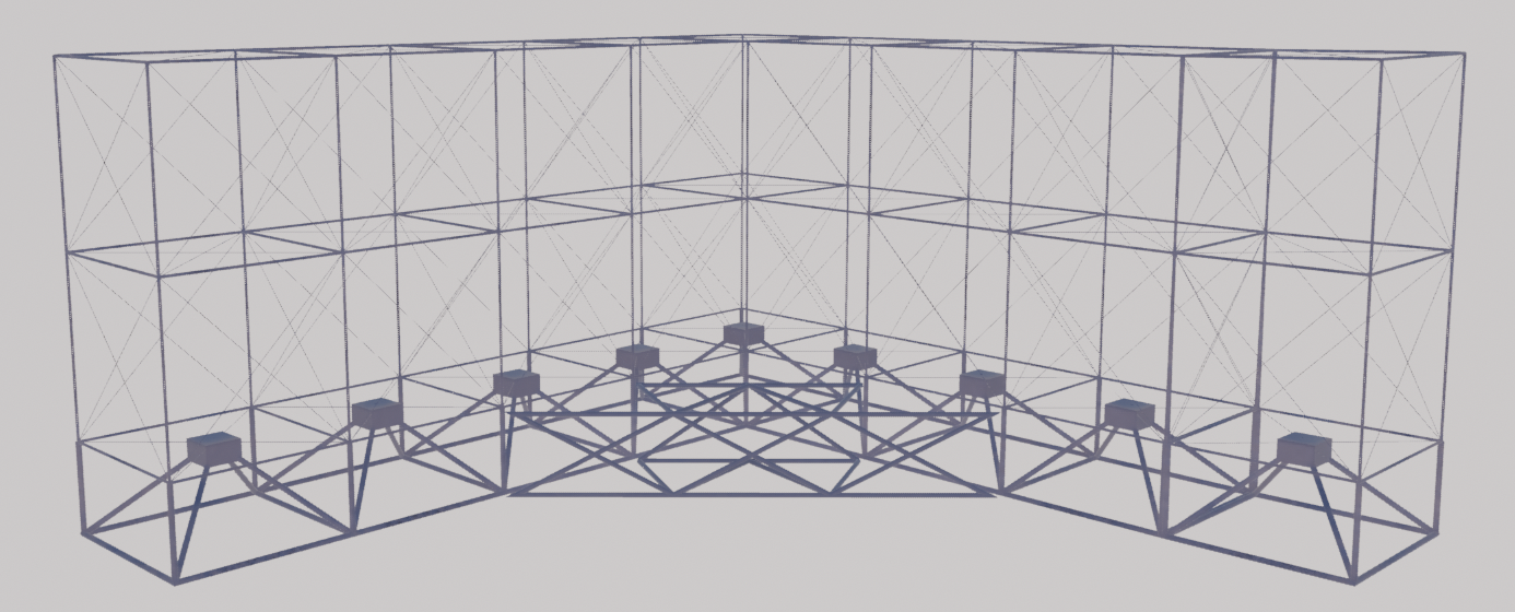
The floating platform directly beneath the turbines consist of an additional row of frames:
These lower frames are similar in concept to the turbine cubes, but:
They are proportioned for buoyancy and global stiffness rather than blade support.
They use larger tubular members to provide displacement and allow the structure to sit partially submerged.
From the bottom corners of these lower frames:
Four tubular members rise up and converge toward a point near the bottom bearing of the lowest turbine shaft.
These four members form a four‑sided pyramid in each frame bay.
They act as compression elements, tying the buoyant structure firmly to the turbine shaft region, improving stiffness and load paths.
This arrangement, combining:
The cube frames,
The pyramid struts, and
The underlying Prestressed Truss Beam principles,
This arrangement has been analyzed and found to provide a robust, efficient load‑carrying structure for large floating arrays in a turbulent ocean environment .
Prestressed Truss Beams: high compression capacity with modest weight
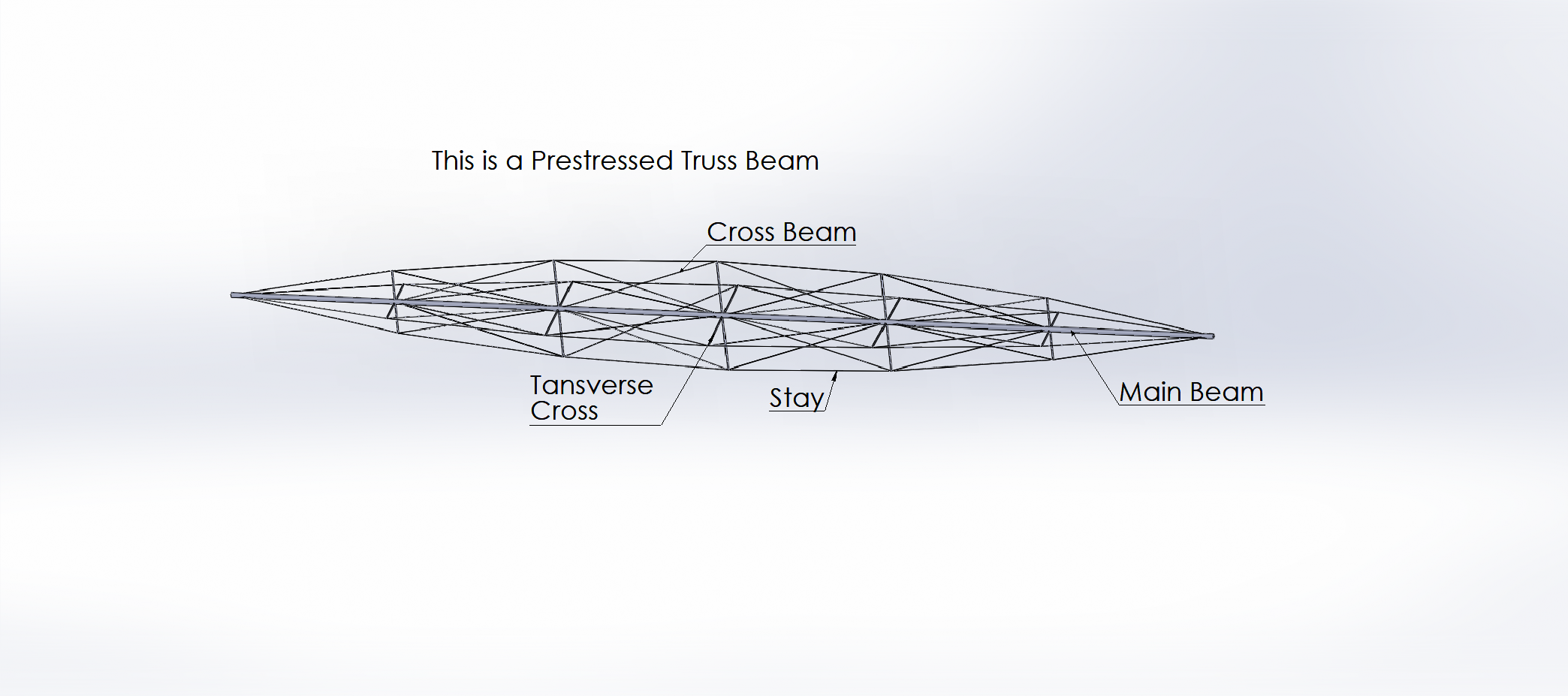
Long, slender beams normally fail in buckling when placed in compression, especially in horizontal applications. To address this, Lux Wind Power uses a Prestressed Truss Beam (PTB):
A main compression member runs the full length of the beam.
Transverse cross beams are placed at intervals along this main member.
Stays (tension members) run from each end of the main beam to the ends of the cross beams.
Additional members cross between the cross beams, and these are also in tension.
When used horizontally, a thicker lower stay carries higher tension, keeping the main beam straight even under very high compression.
In a PTB:
All stays and cross bracing are in tension.
The main member is always in compression, with greatly reduced tendency to buckle.
Analysis shows that a PTB can carry about 18 times the compression load that Euler’s buckling formula would allow for a similar slenderness, with only around 33% increase in weight.
This PTB concept underlies:
The long horizontal and diagonal members in the floating space frame.
The pyramid struts connecting the floating frames to the turbine shafts.
It is one of the key reasons why the structure can remain slim yet strong at the scales required for an 80 MW platform.
Central pivot and tethers to align with the wind and reduce structural stress
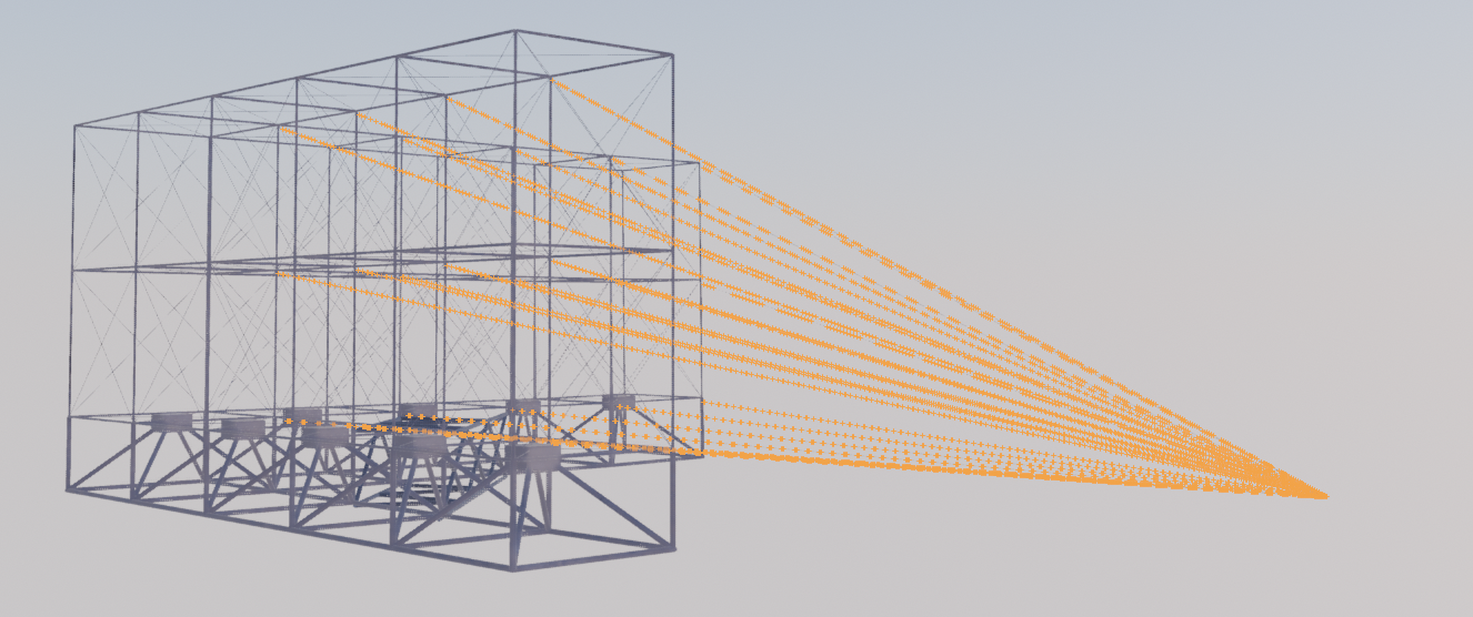
The Tethers are high lighted in orange for visibility.
Rather than relying on a complex yaw system, the V‑array is designed to naturally face the wind:
Inside the V, tether lines run from the inner corners of each frame to a common point at or near the water surface.
From this common point, a single main line runs down to the seabed.
This creates a pivot point about which the entire V‑array can rotate, allowing the structure to stay into the wind.
These tethers serve two purposes:
Automatic alignment:
The array passively turns to face the incoming wind, keeping the V‑shape correctly oriented without active yaw control.Load sharing:
The tethers carry a portion of the aerodynamic thrust load, so the beams and frames do not have to resist all wind forces alone. This reduces stress in the structural members and can improve fatigue life.
The V‑shape, combined with the pivot and tether system, is intended as a high‑level architecture. Detailed mooring design and dynamic analysis are left for experienced offshore engineering partners who will adapt the concept to specific sites and water depths.
Concept stage, with a proven structural core
The Lux Wind Power technology is at the stage where:
The underlying structural concepts — cube‑framed VAWTs, stacked common‑shaft modules, and Prestressed Truss Beams — are proven at prototype scale on land.
The overall 80 MW floating V‑array arrangement has been defined and analyzed at a conceptual level.
Array interaction effects (V angle and spacing) have been investigated on a smaller test array, confirming that geometry can significantly affect total output.
What remains is the work that major turbine and offshore companies are well equipped to perform:
Full hydrodynamic and structural analysis of the floating array.
Optimization of turbine spacing, V angle, and mooring for specific environments.
Integration with your preferred turbine designs, generators, and controls.
Certification, industrialization, and commercialization.
Lux Wind Power’s goal is to provide the architecture and IP, not to build and sell hardware.